The build begins & tapping aluminium extrusions

I ordered the wrong size self-tapping screws (M5 instead of M6), so I had to tap the aluminium extrusions manually.

I changed my BOM so nobody else has the problem.

Tapping threads into aluminium extrusion by hand
Self-tapping screws and aluminium extrusion pieces
VORON printed parts laid out on workbench
Close-up of tapped aluminium extrusion ends
Initial VORON parts and hardware spread on table
Tapping tool in an aluminium V-Slot extrusion

Installing frame & motors + first problem

Today I finally installed the frames and mounted the motors.

Also wanted to mount the A&B idlers but unfortunately the steel dowels have a diameter of 5mm and the inner diameter of the flanged bearings have an inner diameter of 4,96mm.

Already ordered new dowels with a diameter of 4mm. I updated the BOM accordingly.

V-Slot extrusions cut to length for the frame
V-Slot frame rails arranged before assembly
Frame extrusions with corner brackets attached
Assembled VORON rectangular frame structure
Frame with motors mounted to the corners
Stepper motor mounted on the VORON frame
Motor A and B mounted on the aluminium frame
Steel dowels and flanged bearings for idlers
A and B idler pulleys and hardware
Idler assembly with bearings on steel dowel
Close-up of idler bearing fit on dowel
Frame assembly with motors and idlers in place
VORON frame viewed from above with installed components
Completed frame and motor assembly overview

Installing Motor Mounts

I installed the motor mounts. The parts for motor B fitted well, but motor A I have to print again (nut traps were too tight).

3D-printed motor mount installed on frame
Motor mount B fitted on the VORON frame

Assembling the X carriage and mounting it to the Y rails

I assembled the X carriage and was absolutely amazed by this awesome design work. The nozzle probe works like a charm. Kudos russiancatfood!

While installing the “Chimera” hotend clone I found out that one of the heatbreak rods is stuck in the heatsink. I guess it will work, but I hope I can get the money back from the Chinese vendor.

X carriage parts before assembly
X carriage assembled with belt path visible
X carriage mounted on the Y rails
X carriage with nozzle probe mechanism
Nozzle probe detail on the X carriage
Chimera hotend clone installed on the carriage
Chimera hotend heatsink with heatbreak rods
Close-up of the Chimera hotend heatbreak
X carriage wiring with connectors visible
Wiring harness and electronics on the VORON

Final assembly, first time pushing plastic

Worked yesterday 11 hours on my VORON and got it to push plastic :-)

The cable harness is still a mess, need some more time to clean up and calibrate.

I want to make the cables on my carriage unplugable, but my connectors didn’t arrive yet. So I used some “WAGO” clamps.

VORON printer fully assembled for first test
First extrusion test with filament coming out
Cable harness mess behind the VORON printer
WAGO clamps used for temporary wiring connections
VORON electronics board with WAGO wire connections
VORON printer running its first plastic extrusion
First layer being laid down on the print bed
VORON printer first print in progress at night
Completed first test print result

Dial indicator bed leveling

I created a dial indicator mount to level my bed more precisely. Works like a charm…

You can download the model from thingiverse: https://www.thingiverse.com/thing:2347217

3D-printed dial indicator mount on the X carriage
Dial indicator probing the print bed surface
Dial indicator reading during bed leveling
Bed leveling adjustment with dial indicator mounted
Dial indicator mount design on the hotend assembly

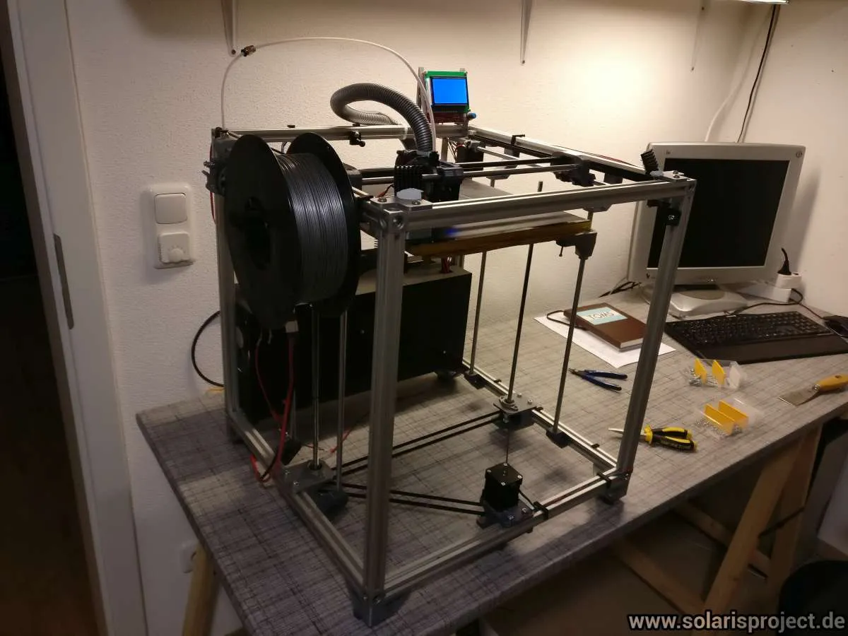
Finalized the build (or I thought so)

It took some time but I am finished with my VORON build. Just wanted to show the current state of build.

I am not quite happy with the cable management. I will probably buy myself a sheet of wood and put it on the backside of the VORON and attach to the sheet all the electrical stuff.

Let’s see what the future brings :-)

Completed VORON 1.5 printer overview
VORON printer front view with electronics visible
VORON printer side view showing cable management
Electronics controller board mounted on the back
Close-up of controller board wiring and connections
Rear view of electronics and power supply

Final result (still WIP)

I had some time to do my “final” adjustments to my VORON. The black boxes in the back annoyed me, so (as announced) I replaced it with a sheet of plywood and mounted there my controller stuff.

Additionally I replaced the part cooling fan duct by my own design, now I can use a silent 60mm SUNON axial fan. I published the custom fan duct on Thingiverse:

https://www.thingiverse.com/thing:2332578

VORON printer with plywood electronics mount
Controller electronics on plywood back panel
Custom 60mm SUNON fan duct on the hotend
Custom part cooling fan duct installed on carriage
Completed VORON 1.5 printer final build photo